
Since having a PV (Photo Voltaic) solar array installed on my roof earlier in the year I have become a more aware of the energy consumption of my house.
In my post ‘Making Data Driven Decisions With A PV Array, Home Assistant and MQTT‘ I am leveraging consumption data to make decisions in my house, and this has only continued since the time I authored this post.
How-ever, I often ask myself 2 simple questions at home
- How much power is my house generating?
- Is electricity free? In another words, am I exporting to the grid and if so, how much?
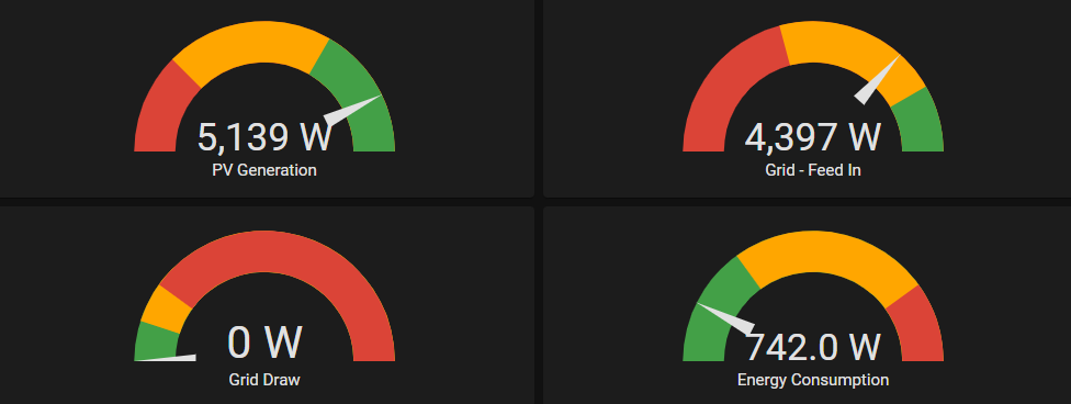
Before I go any further, let’s get straight to a demo, so you can determine if you should continue reading.
Decided to read on?
Both of these questions I can answer, but it involves either using a phone or laptop leveraging some customer Home Assistant Lovelace cards I made.
Is there a way I could understand this without the need of my phone or laptop?
Yes, there is! Tri-Colour Emitting Diodes or RGB LED’s
In this post I am going to illustrate how with less than $30AUD worth of parts you can visualise power consumption in your solar array in the form of lights that change colors.
Worth noting, in order to visualise consumption and feed-in, you will need to have a means to measure this. I am using a SMA Energy Meter to measure, but the same principal applies to any solar PV system.
This article will illustrate how to
– Push messages from Home Assistant to a MQTT Topic via MQTT StateStream
– Leverage an Arduino compliant MCU (Microcontroller) to read messages from a MQTT topic
– Drive RGB LED’s based on the values of MQTT Topics
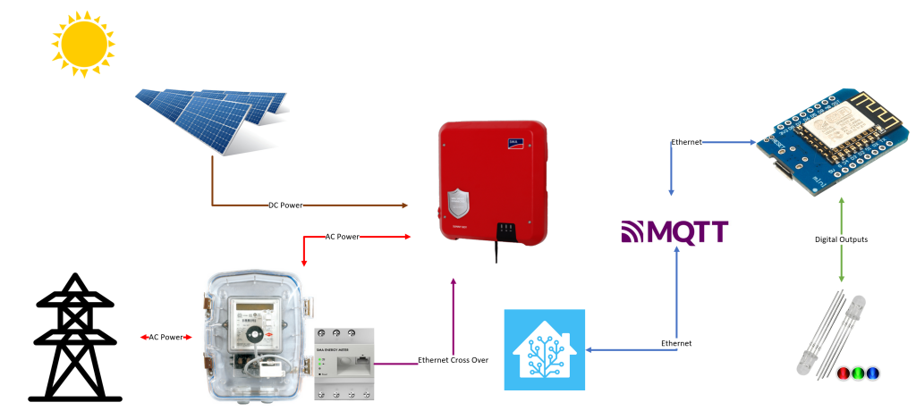
The image below should help visualise the end-to-end flow.
Bill of Materials
– 2 x 5MM 4Pin RGB Tri-Colour Emitting Diodes Common Anode/Cathode LED Lights ($5 AUD for 10)
– 1 x Wemos D1 Mini/Mini Pro 16MB ESP8266/ESP12 WiFi NodeMCU ($7 AUD)
– 6 x 300ohm resistors ($3 AUD for 50 units)
– 1 x length of heat shrink ($3 AUD)
– 22 gauge cable between Wemos and LED’s, approx 5m ($3 AUD)
– Plastic transparent plugs ($2 AUD)
Total Cost = $23
Tools used
– Soldering Iron
– Drill and drill bits
An RGB Back Story – How do you make colours?
With RGB LED’s containing 3 channels using PWM or Pulse Width Modulation allows the MCU to adjust the duty cycle to the LEDs so we can get the desired colors. This is very similar to a HTML colour code, these 3 values in effect allow you create a variety of colours.

Each primary colour is a specific output on the Wemos, and I am sharing a common cathode. This diagram below is for 1 LED, scale this for the number of LED’s you wish to drive.

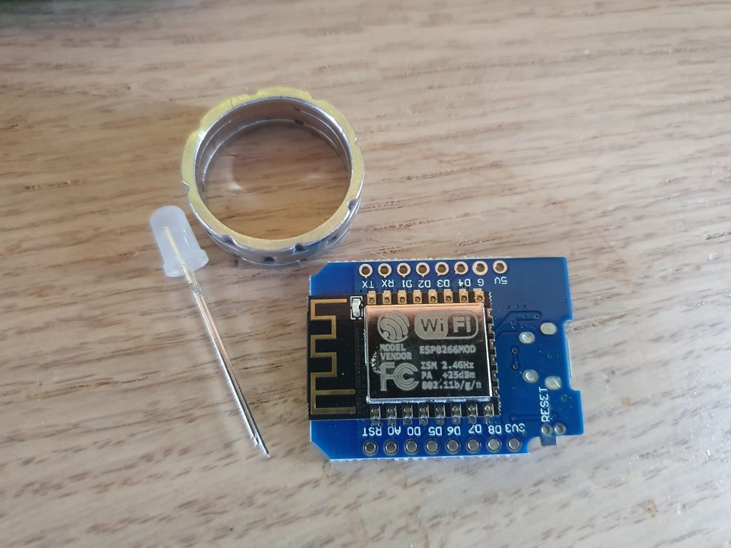
Step 1: Gather a Suitable MicroController
I choose rather than running cable from my telco rack to use a dedicated MCU. An ESP8266 / ESP32 are my devices of choice in these applications. Cheap, have WiFi and are Arduino compliant.
I am using a Wemos D1 Mini. It has enough I/O for my 2 LED’s and speaking of LED’s these are 4 pin RGB Tri-Colour diodes, meaning with PWM (Pulse Width Modulation) allowing myself to vary the intensity of any given LED from 0-255, there is an ability to make almost any color.
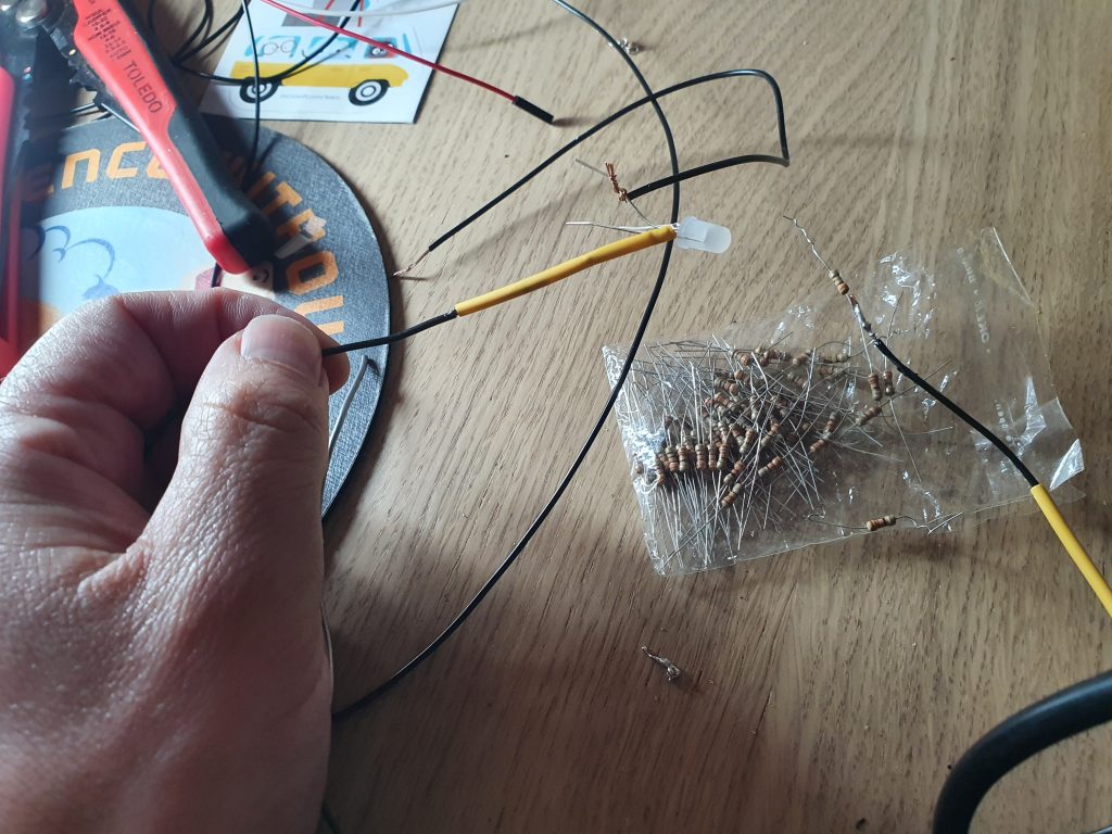
Step 2: Wire everything up
Each LED has 4 legs, the longest leg, being the cathode to ground.
Solider the anode to ground and for each leg, put in-line a 300ohm resistor. Because the ground is common, this can be looped from one LED to another. I use heat shrink over ever solider connection and then use a cable sheath to give that neat look.
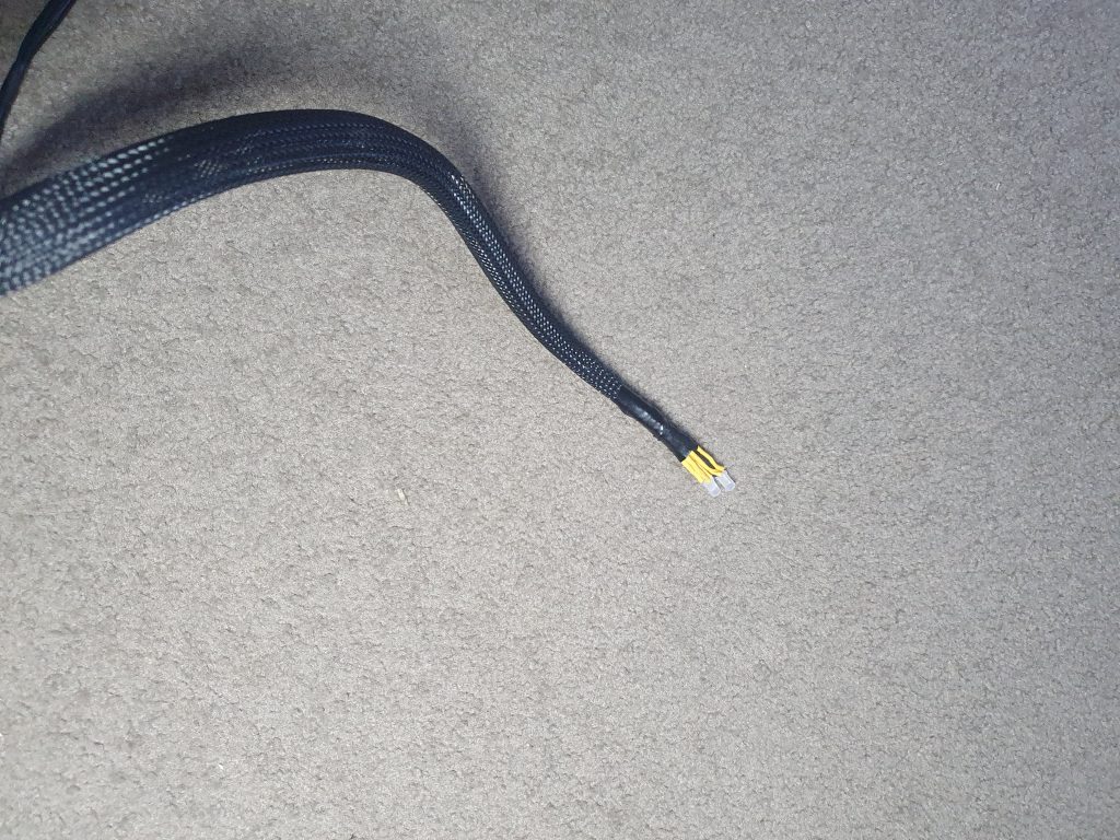
Insert the LED hardness and get to coding. Right now we have wired this up physically but there is no code to either drive the LED’s or to read data from my Smart Meter / Home Assistant.
Step 3 : Home Assistant and MQTT
The energy consumption and feed in data needs to be able to be consumed by the Wemos via MQTT. The SMA Smart Energy meter provides a HTTP based REST interface which Home Assistant consumes. In order to publish sensor data to a MQTT topic we can use MQTT StateStream. This integration publishes state changes in Home Assistant to individual MQTT topics. The MQTT integration is a prerequisite for MQTT Statestream to work.
Below is an extract taken from my configuration.yaml
mqtt_statestream:
  base_topic: homeassistant
  include:
   entities:
      - sensor.metering_active_power_feed_l1
      - sensor.energy_house_consumption
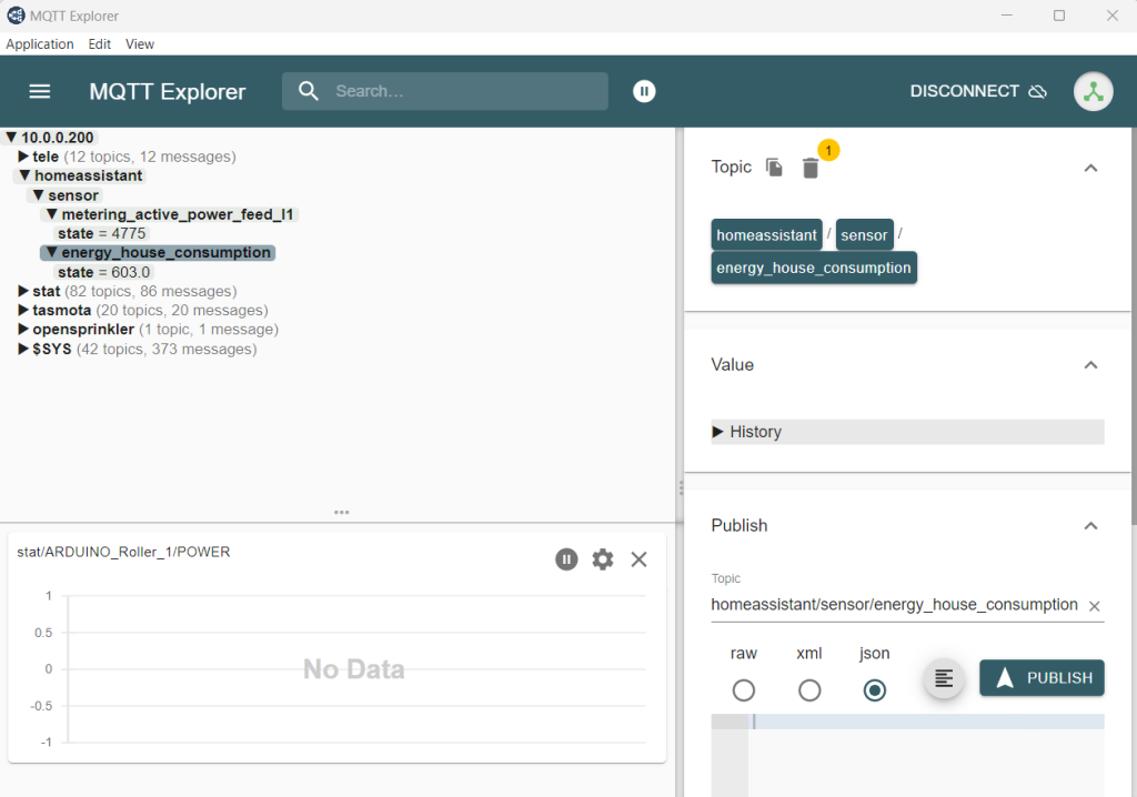
Every time there is a change to these values, they are published to the “/homeassistant/sensor” topic
Step 4: Time for some code
Physically wired up with consumption data flowing to our MQTT topics, we now need to author some code to make these LED’s change colour based on the load. I will step through this process along with leaving a full code snippet. The main loop contains my logic on at what values to change lights on and to what colours.
Include MQTT and Wifi libaries
#include <PubSubClient.h>
#include <ESP8266WiFi.h>
Define variables, such as PIN mappings, Wifi connection details and MQTT string values
int feed_in_red_light_pin= 5;
int feed_in_green_light_pin = 4;
int feed_in_blue_light_pin = 0;

int consumption_red_light_pin= 2;
int consumption_green_light_pin = 12;
int consumption_blue_light_pin = 15;

const char* ssid = "Your SSID";
const char* pswd = "Your Password";
const char* mqtt_server = "Your MQTT Server";

String MQTTTopic;
String MQTTPayload;
String IPAddress;
WiFiClient espClient;
PubSubClient client(espClient);
long lastMsg = 0;
int value = 0;
int status = WL_IDLE_STATUS;     // the starting Wifi radio's status
The setup function
void setup() {
  Serial.begin(9600);
  setup_wifi();
  client.setServer(mqtt_server, 1883);
  client.setCallback(callback);

  pinMode(feed_in_red_light_pin, OUTPUT);
  pinMode(feed_in_green_light_pin, OUTPUT);
  pinMode(feed_in_blue_light_pin, OUTPUT);
}
Messages will be received via MQTT, the following functions deal with connection, callbacks, character conversion and topic subscriptions. Thie callback function is where I am constructing the character payload into a string, which will be converted into an integer and used for evaluation.
void callback(char* topic, byte* payload, unsigned int length) {
  MQTTTopic = String(topic);
  MQTTPayload = "";
  Serial.println("T [" + MQTTTopic +"]");
  for (int i = 0; i < length; i++) {
    MQTTPayload = String(MQTTPayload + (char)payload[i]);
  }
  Serial.println("P [" + MQTTPayload + "]");
}

String macToStr(const uint8_t* mac)
{
  String result;
  for (int i = 0; i < 6; ++i) {
    result += String(mac[i], 16);
    if (i < 5)
      result += ':';
  }
  return result;
}

String composeClientID() {
  uint8_t mac[6];
  WiFi.macAddress(mac);
  String clientId;
  clientId += "esp-";
  clientId += macToStr(mac);
  return clientId;
}

void reconnect() {
  // Loop until we're reconnected
  while (!client.connected()) {
    Serial.print("Attempting MQTT connection...");

    String clientId = composeClientID() ;
    clientId += "-";
    clientId += String(micros() & 0xff, 16); // to randomise. sort of

    // Attempt to connect
    if (client.connect(clientId.c_str())) {
      Serial.println("connected");
      // Once connected, publish an announcement...
      client.publish("stat/WemosD1-Study/IpAddress","10.0.0.40");
      //Subscribe
      client.subscribe("homeassistant/sensor/metering_active_power_feed_l1/state");
      Serial.println("");
      Serial.print("Subscribed to : homeassistant/sensor/metering_active_power_feed_l1/state ");
      client.subscribe("homeassistant/sensor/energy_house_consumption/state");
      Serial.println("");
      Serial.print("Subscribed to : homeassistant/sensor/energy_house_consumption/state ");
    } else {
      Serial.print("failed, rc=");
      Serial.print(client.state());
      Serial.print(" wifi=");
      Serial.print(WiFi.status());
      Serial.println(" try again in 5 seconds");
      // Wait 5 seconds before retrying
      delay(5000);
    }
  }
}
Functions for controlling the RGB value of each LED with PWM values that are called in the main loop
void feed_in_RGB_color(int red_light_value, int green_light_value, int blue_light_value)
 {
  analogWrite(feed_in_red_light_pin, red_light_value);
  analogWrite(feed_in_green_light_pin, green_light_value);
  analogWrite(feed_in_blue_light_pin, blue_light_value);
 }


 void consumption_RGB_color(int red_light_value, int green_light_value, int blue_light_value)
 {
  analogWrite(consumption_red_light_pin, red_light_value);
  analogWrite(consumption_green_light_pin, green_light_value);
  analogWrite(consumption_blue_light_pin, blue_light_value);
 }
And wrapping this all together is the main loop.
void loop() {
  // confirm still connected to mqtt server
  if (!client.connected()) {
    reconnect();
  }
  client.loop();
  if (MQTTTopic == "homeassistant/sensor/metering_active_power_feed_l1/state") {

    if (MQTTPayload.toInt() == 0)  {
      feed_in_RGB_color(255, 0, 0); // Red
    // Serial.println("Changing to red");
    }
      else if (MQTTPayload.toInt() > 0 && MQTTPayload.toInt() < 251) {
      feed_in_RGB_color(255, 0, 255); // Magenta = Error
      //  Serial.println("Changing to magenta");

    }
    else if (MQTTPayload.toInt() > 250 && MQTTPayload.toInt() < 501) {
      feed_in_RGB_color(0, 0, 255); // Blue
      //  Serial.println("Changing to blue");

    }
    else if (MQTTPayload.toInt() > 500 && MQTTPayload.toInt() < 1001) {
      feed_in_RGB_color(0, 255, 255); // Cyan
      //  Serial.println("Changing to cyan");
    }
    else if (MQTTPayload.toInt() > 1000 && MQTTPayload.toInt() <= 2500) {

        feed_in_RGB_color(255, 255, 0); // Yellow
    // Serial.println("Changing to yellow");
    }
    else if (MQTTPayload.toInt() > 2500) {
        feed_in_RGB_color(0, 255, 0); // Green
      //  Serial.println("Changing to green");
      }
  }

// House Consumtpion
   if (MQTTTopic == "homeassistant/sensor/energy_house_consumption/state") {

    if (MQTTPayload.toInt() > 0 && MQTTPayload.toInt() < 401) {
      consumption_RGB_color(0, 255, 0); // Green


    }
    else if (MQTTPayload.toInt() > 400 && MQTTPayload.toInt() < 501) {
      // Serial.println("Changing to yellow");
        consumption_RGB_color(255, 255, 0); // Yellow

    }
      else if (MQTTPayload.toInt() > 500 && MQTTPayload.toInt() < 1001) {
              consumption_RGB_color(0, 255, 255); // Cyan
        //  Serial.println("Changing to cyan");


    }
    else if (MQTTPayload.toInt() > 1000 && MQTTPayload.toInt() <= 2001) {
            consumption_RGB_color(0, 0, 255); // Blue
      //  Serial.println("Changing to blue");


    }
    else if (MQTTPayload.toInt() > 2000 && MQTTPayload.toInt() <= 3001) {
               consumption_RGB_color(255, 0, 255); // Magenta
    }
    else if (MQTTPayload.toInt() > 3000) {
      // Serial.println("Changing to red");

        consumption_RGB_color(255, 0, 0); // Red
      //  Serial.println("Changing to red");
      }
  }

}
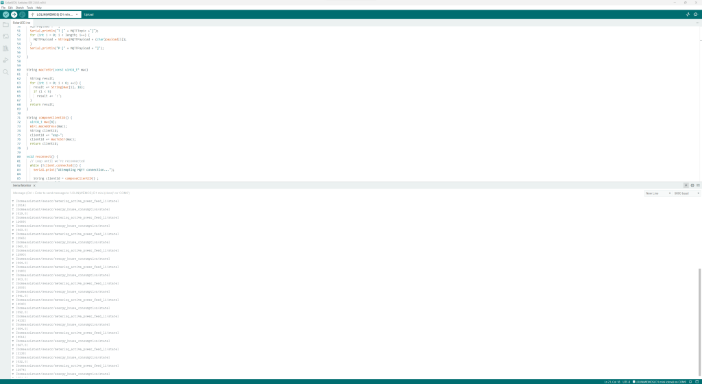
The entire code snippet can be found in my GitHub repository and after loading the sketch, the serial output will illustrate the values being read via MQTT. This could easily be expanded to push to the serial stream the colours of the induvial LED’s. How creative are you?
Summary
Sometimes even with all this amazing technology we have, a visual indicator is far better and easier than using a phone or a computer. In my case, this just ticks away and does its job.
Consider how you can simplify your technology journey, be it personal or for your company. Technology needs to be accessible for the value to be derived by all parties.
In this example, has it changed how we consume power in our house, a little bit. It means without energy storage at home, I am able to quickly tell if our consumption exceeds generation.
But more so, I do this because I can, and it is an excellent example of how protocols, such as MQTT can democratize data and ensure it is able to be consumed by other disparate systems.
Think big and stay creative.
Shane
Nice, where do you get your ESP32s from? Do you have an enclosure or mounting bracket for it to keep it out of the way? Also do you have any photos of the finished thing? 😀
You made me clean my desk 😉
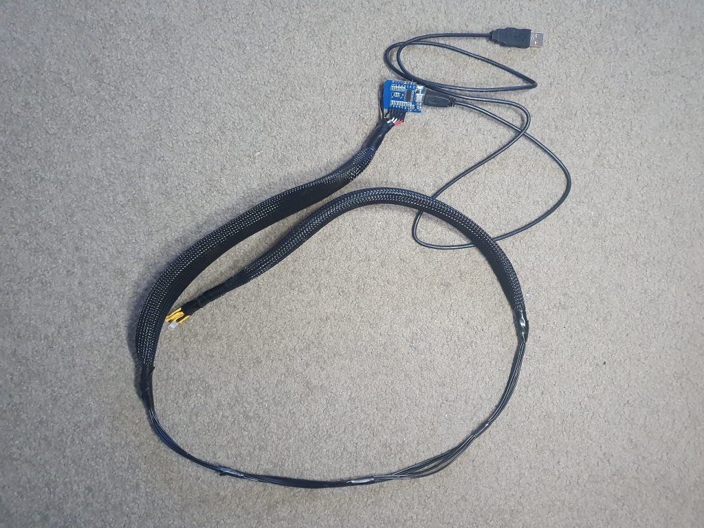
I get my ESP32’s really anywhere, eBay often. I have no enclosure, nothing is free hanging off a piece of coiled micro-usb cable which powers the device from a screens USB hub. I plan to add I2c and a 1602a LCD screen.
The weight of the loom is suspended by the USB cable. Thus far no issues ever
Thanks for the question
Shane