A few months ago, I solved the problem of having to use a Home Assistant dashboard to view power related metrics that matter to me by using LED’s embedded into my desk. You can read about it here, and these LED’s work really well. The LED’s have saved me looking at Home Assistant, and they answer broadly speaking my questions around exporting and generation of power.
Never content with the status quo, but more so, wanting to learn more about SPI, i2C and LCD screens I thought, how could I leverage this desire as a learning opportunity to take this to the next level.
In this post I will illustrate how to
– How to connect a 1602 LCD display to a I2C interface
– Connect your I2C interface to an Arduino based MCU
– Create C++ code, to display content from a MQTT topic subscriptions.
If this sounds like something you wish to know more about, then please read on.
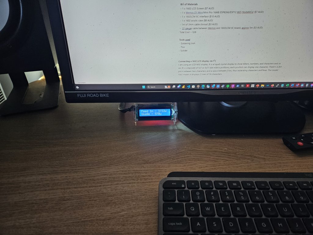
Bill of Materials
– 1 x 1602 LCD Screen ($7 AUD)
– 1 x Wemos D1 Mini/Mini Pro 16MB ESP8266/ESP12 WiFi NodeMCU ($7 AUD)
– 1 x 1602LCM IIC interface ($10 AUD)
– 1 x 1602 acrylic case ($8 AUD)
– 1m of 3mm cable shroud ($3 AUD)
– 22 gauge cable between Wemos and 1602LCM IIC board, approx 5m ($3 AUD)
Total Cost = $38
Tools used
– Soldering Iron
– Flux
– Solder
Connecting a 1602 LCD display via I2C
I am using an LCD1602 display. It is a liquid crystal display to show letters, numbers, and characters and so on. It’s composed of 5×11 dot matrix positions; each position can display one character. There’s a dot pitch between two characters and a space between lines, thus separating characters and lines. The model 1602 means it displays 2 lines of 16 characters.
The 1602 has parallel data ports, that is, you control several pins at the same time. With 8 data lines in use, depending on your MCU being used, you may use all, or a considerable number of digital pins.
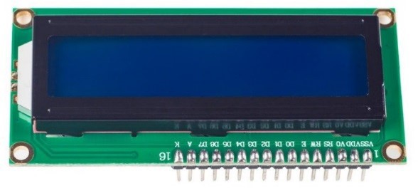
The pin-out’s can be described by viewing the following table.
| Pin | Function |
| VSS | Connected to ground |
| VDD | Connected to a +5v DC PSU |
| RS | A register select pin that controls where in the LCD’s memory you are writing data to. You can select either the data register, which holds what goes on the screen, or an instruction register, which is where the LCD’s controller looked for instructions on what do to next |
| R/W | A Read/Write pin to select between reading and writing mode |
| E | An enabling pin that reads the information when High (level 1) is received. Instruction are run when the signal changes from High to Low |
| D0-D7 | To read and write data |
| A | A pin that controls the LCD backlight/ Connect A to +3.3VDC |
| K | A pin that controls the LCD backlight. Connect K to GND |
| VO | Contrast adjustment |
Wiring this screen to an Arduino MCU results in the following schematic, there are a lot of data lines that are required, and given this device is already driving LED’s, I did not have free on my Wemos D1 based MCU
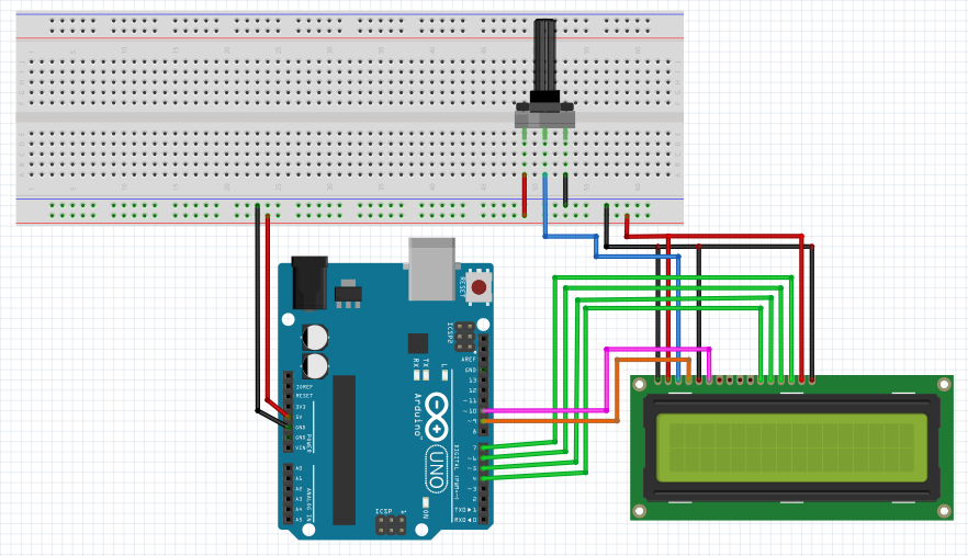
https://www.diyengineers.com/2021/01/07/learn-how-to-use-the-1602-lcd-with-arduino/
An I2C backstory, lets talk about I2C
There is another way, and I think it’s worthwhile spending a bit of time digressing. that reduces the number of digital pins to just two using I2C (Inter-Integrated Circuit), a more modern way, even if it is now 40+ years old. I have been using I2C in PLC’s for years now and they are great way
I2C (pronounced as “eye-squared-C”), alternatively known as I2C or IIC, is a synchronous, multi-master/multi-slave (controller/target), packet switched, single-ended, serial communication bus invented in 1982 by Philips Semiconductors. It is widely used for attaching lower-speed peripheral ICs to processors and microcontrollers in short-distance, intra-board communication. You can still see in 2023 I2C being used by light sensors in laptops and phones when low bandwidth serial communication is needed.
I2C uses only two bidirectional open-collector or open-drain lines: serial data line (SDA) and serial clock line (SCL), pulled up with resistors. Typical voltages used are +5 V or +3.3 V, although systems with other voltages are permitted.
The number of nodes which can exist on a given I2C bus is limited by the address space and also by the total bus capacitance of 400 pF, which restricts practical communication distances to a few meters. The relatively high impedance and low noise immunity requires a common ground potential, which again restricts practical communication distances.
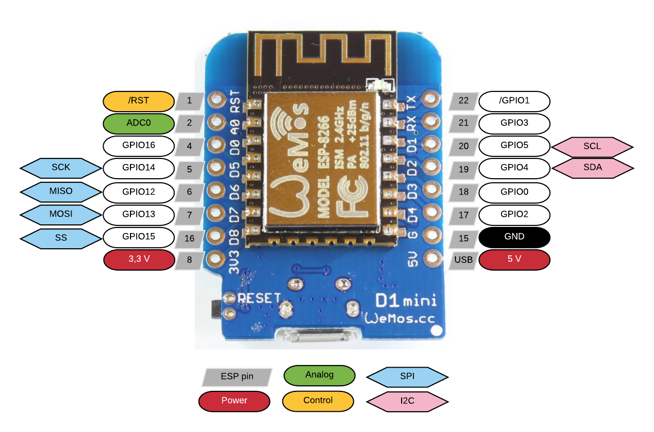
I am using a LCM1602 IIC device to provide I2C communication between my Arduino compliant MCU (A Wemos D1 Mini Clone) and the 1602 LCD screen. This device is then soldered to the female inputs on the 1602 LCD
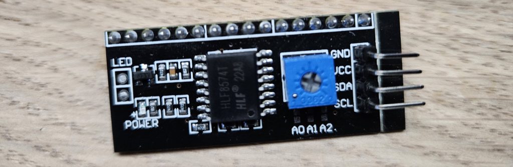
By leveraging the LCM1602 IIC, I am able to reduce the data lines to just two by using the SCL and SDA outputs.
The example below is using and Arduino Uno, but note the location of SCL and SDA outputs on your MCU will differ and as a result I would suggest you use your favourite search engine and search for ‘Your MCU Pinout’. As this is a bus, typically there will only be one SCL and SDA compliant pin on your MCU.

Once physically connected, we need to determine the logical address of the LCM 1602 IC
Determining Our I2C Address
The LCM1602 IIC boards can come with I2C chips from both Texas Instruments and NXP Semiconductors, both have different default I2C addresses. You can also change this value soldering contacts on the backside. You could probably guess in code what your address is and via trial and error, however you can query the address. I used the following sketch to scan the I2C bus for the address of my device. Run this sketch and note the address, you will need this soon.
#include <Wire.h>

void setup() {
  Wire.begin();

  Serial.begin(9600);
  while (!Serial); // Leonardo: wait for serial monitor
  Serial.println("\nI2C Scanner");
}

void loop() {
  int nDevices = 0;

  Serial.println("Scanning...");

  for (byte address = 1; address < 127; ++address) {
    // The i2c_scanner uses the return value of
    // the Write.endTransmisstion to see if
    // a device did acknowledge to the address.
    Wire.beginTransmission(address);
    byte error = Wire.endTransmission();

    if (error == 0) {
      Serial.print("I2C device found at address 0x");
      if (address < 16) {
        Serial.print("0");
      }
      Serial.print(address, HEX);
      Serial.println("  !");

      ++nDevices;
    } else if (error == 4) {
      Serial.print("Unknown error at address 0x");
      if (address < 16) {
        Serial.print("0");
      }
      Serial.println(address, HEX);
    }
  }
  if (nDevices == 0) {
    Serial.println("No I2C devices found\n");
  } else {
    Serial.println("done\n");
  }
  delay(5000); // Wait 5 seconds for next scan
}
Authoring Code For Displaying Metrics
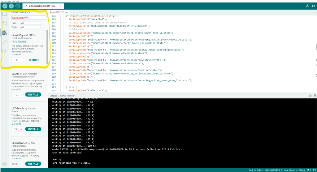
In order to interface with our 1602LCD over I2C we need to add a library. In ‘Library Manager’ perform a search and install ‘LiquidCrystal I2C’
LiquidCrystal_I2C Basics
Let me explain a few of the basics of this library, these are the functions I am using, there is a lot more. For more depth including custom characters, see the Arduino reference guide for this library.
The sketch begins by including the LiquidCrystal_I2C library.
#include <LiquidCrystal_I2C.h>
The next step is to create an object of LiquidCrystal_I2C class. The LiquidCrystal_I2C constructor accepts three inputs: I2C address, number of columns, and number of rows of the display. My address which I validated with our scanning sketch is 0x27
LiquidCrystal_I2C lcd(0x27,16,2);
In the setup, three functions are called. The first function is init(). It initializes the interface to the LCD. The second function is clear(). This function clears the LCD screen and positions the cursor in the upper-left corner. The third function, backlight(), turns on the LCD backlight.
lcd.init();
lcd.clear();
lcd.backlight();
The function setCursor(2, 0) is then called to move the cursor to the third column of the first row. The cursor position specifies where you want the new text to appear on the LCD. It is assumed that the upper left corner is col=0 and row=0.
lcd.setCursor(2,0);
Next, the print() function is used to print “Hello world!” to the LCD.
lcd.print("Hello world!");
My code in essence is displaying messages being received over MQTT. In this post I detail how pushing metrics from my solar PV array on to a MQTT topic. In order to display solar generation, solar consumption, solar feed-in and temperature I am using MQTT State Stream in Home Assistant and my configuration.yaml has the following.
mqtt_statestream:
  base_topic: homeassistant
  include:
   entities:
      - sensor.metering_active_power_feed_l1
      - sensor.metering_active_power_draw_l1
      - sensor.energy_house_consumption
      - sensor.downstairs
      - sensor.outside
This manifests itself as updates being published at a frequency of no more than 1hz
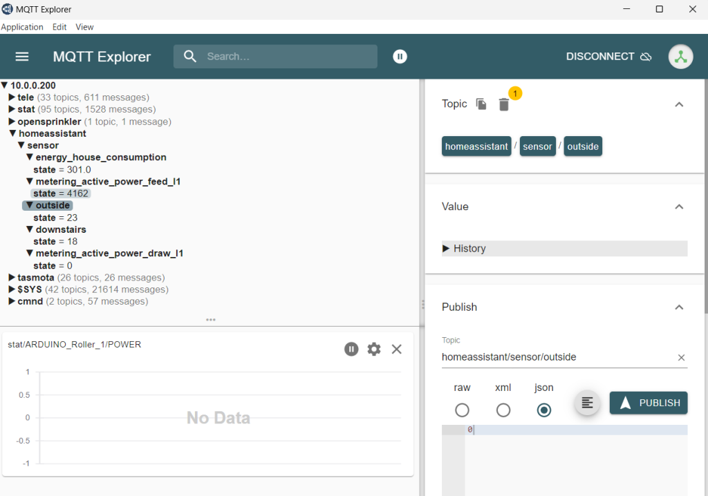
In order to get this data, we need to subscribe to our interested topics.
client.publish("stat/WemosD1-Study/IpAddress","10.0.0.40");
//Subscribe
client.subscribe("homeassistant/sensor/metering_active_power_feed_l1/state");
Serial.println("");
Serial.print("Subscribed to : homeassistant/sensor/metering_active_power_feed_l1/state ");
client.subscribe("homeassistant/sensor/energy_house_consumption/state");
Serial.println("");
Serial.print("Subscribed to : homeassistant/sensor/energy_house_consumption/state ");
client.subscribe("homeassistant/sensor/downstairs/state");
Serial.println("");
Serial.print("Subscribed to : homeassistant/sensor/downstairs/state ");
client.subscribe("homeassistant/sensor/outside/state");
Serial.println("");
Serial.print("Subscribed to : homeassistant/sensor/outside/state ");
client.subscribe("homeassistant/sensor/metering_active_power_draw_l1/state");
Serial.println("");
Serial.print("Subscribed to : homeassistant/sensor/metering_active_power_draw_l1/state ");
I am going to paste my entire sketch below. Your use cases will vary but I hope you can see how this works and to use what works for you. It is a pattern that you can apply to your own use cases. What this code demostrates is
- Subscribing to MQTT Topics
- Reading payloads from MQTT via call backs
- Leveraging the LiquidCrystal I2C library
- Using millis timers
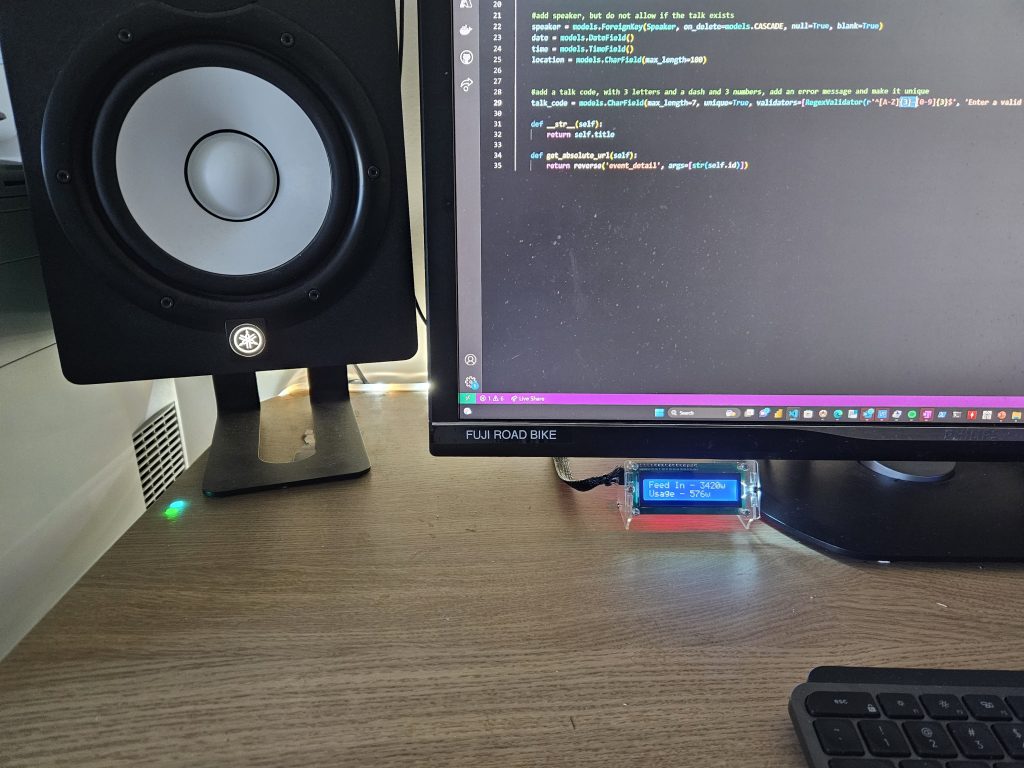
In my use, I am driving two LED’s based on solar metrics but am also now displaying metrics on a 1602 LCD display via I2C.
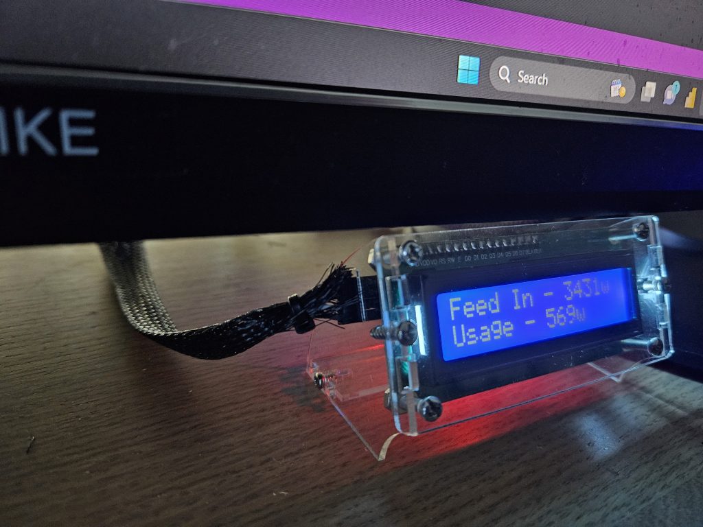
On Line 0 I display the amount of watts I am feeding in to the grid. If there is no feed-in value, because its dark or I am using more power than I generate, this line display’s the grid draw. The second line (Line 1) displays the total house consumption in watts.
Every 10 seconds, the temperate of outside and our downstairs is displayed for 3 seconds.
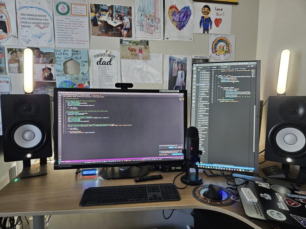
My code is below as is, there are more ways to do this, but it does work and has been stable for the last month. I am running this on a Wemos Mini D1 Clone.
#include <PubSubClient.h>
#include <ESP8266WiFi.h>
#include <LiquidCrystal_I2C.h>

//define I2C address......
LiquidCrystal_I2C lcd(0x27,16,2);

int feed_in_red_light_pin= 1;
int feed_in_green_light_pin = 3;
int feed_in_blue_light_pin = 0;

int consumption_red_light_pin= 2;
int consumption_green_light_pin = 12;
int consumption_blue_light_pin = 15;

const char* ssid = "Your SSID";
const char* pswd = "Your Password";
const char* mqtt_server = "Your MQTT Broker IP";

String MQTTTopic;
String MQTTPayload;
String IPAddress;
String MQTTPayloadLength;
String downstairs_c;
String outside_c;
String feedin_w;
String griddraw_w;
String consumption_w;
WiFiClient espClient;
PubSubClient client(espClient);
long lastTemp=0;
int value = 0;

int status = WL_IDLE_STATUS;     // the starting Wifi radio's status

void setup_wifi() {
  delay(10);
  // We start by connecting to a WiFi network
  Serial.println();
  Serial.print("Connecting to ");
  Serial.println(ssid);
  WiFi.begin(ssid, pswd);
  while (WiFi.status() != WL_CONNECTED) {
    delay(500);
    Serial.print(".");
  }
  Serial.println("");
  Serial.println("WiFi connected");
  Serial.println("IP address: ");
  Serial.println(WiFi.localIP());
}

void callback(char* topic, byte* payload, unsigned int length) {
  MQTTTopic = String(topic);
  MQTTPayload = "";
  Serial.println("T [" + MQTTTopic +"]");
  for (int i = 0; i < length; i++) {
    MQTTPayload = String(MQTTPayload + (char)payload[i]);
  }
  Serial.println("P [" + MQTTPayload + "]");

}


String macToStr(const uint8_t* mac)
{
  String result;
  for (int i = 0; i < 6; ++i) {
    result += String(mac[i], 16);
    if (i < 5)
      result += ':';
  }
  return result;
}

String composeClientID() {
  uint8_t mac[6];
  WiFi.macAddress(mac);
  String clientId;
  clientId += "esp-";
  clientId += macToStr(mac);
  return clientId;
}

void reconnect() {
  // Loop until we're reconnected
  while (!client.connected()) {
    Serial.print("Attempting MQTT connection...");

    String clientId = composeClientID() ;
    clientId += "-";
    clientId += String(micros() & 0xff, 16); // to randomise. sort of

    // Attempt to connect
    if (client.connect(clientId.c_str())) {
      Serial.println("connected");
      // Once connected, publish an announcement...
      client.publish("stat/WemosD1-Study/IpAddress","10.0.0.40");
      //Subscribe
      client.subscribe("homeassistant/sensor/metering_active_power_feed_l1/state");
      Serial.println("");
      Serial.print("Subscribed to : homeassistant/sensor/metering_active_power_feed_l1/state ");
      client.subscribe("homeassistant/sensor/energy_house_consumption/state");
      Serial.println("");
      Serial.print("Subscribed to : homeassistant/sensor/energy_house_consumption/state ");
      client.subscribe("homeassistant/sensor/downstairs/state");
      Serial.println("");
      Serial.print("Subscribed to : homeassistant/sensor/downstairs/state ");
      client.subscribe("homeassistant/sensor/outside/state");
      Serial.println("");
      Serial.print("Subscribed to : homeassistant/sensor/outside/state ");
      client.subscribe("homeassistant/sensor/metering_active_power_draw_l1/state");
      Serial.println("");
      Serial.print("Subscribed to : homeassistant/sensor/metering_active_power_draw_l1/state ");

    } else {
      Serial.print("failed, rc=");
      Serial.print(client.state());
      Serial.print(" wifi=");
      Serial.print(WiFi.status());
      Serial.println(" try again in 5 seconds");
      // Wait 5 seconds before retrying
      delay(5000);
    }
  }
}

void setup() {
  lcd.init();
  lcd.clear();
  lcd.backlight();

  Serial.begin(9600);
  setup_wifi();
  client.setServer(mqtt_server, 1883);
  client.setCallback(callback);

  pinMode(feed_in_red_light_pin, OUTPUT);
  pinMode(feed_in_green_light_pin, OUTPUT);
  pinMode(feed_in_blue_light_pin, OUTPUT);
}

void loop() {
  // confirm still connected to mqtt server
  if (!client.connected()) {
    reconnect();
  }
  client.loop();
  if ( millis() - lastTemp > 10000) {
    lcd.setCursor(0,0);
    lcd.print("Downstairs - " + downstairs_c + "C    ");
    lcd.setCursor(0,1);
    lcd.print("Outside - " + outside_c + "C    ");
    lastTemp = millis();
    delay(3000);
    //lcd.clear();
  }

  if (MQTTTopic == "homeassistant/sensor/outside/state") {
    outside_c = MQTTPayload;
  }
  if (MQTTTopic == "homeassistant/sensor/downstairs/state") {
    downstairs_c = MQTTPayload;
  }


  if (MQTTTopic == "homeassistant/sensor/metering_active_power_feed_l1/state") {
    feedin_w = MQTTPayload;
    lcd.setCursor(0,0);
    lcd.print("Feed In - " + feedin_w + "w    ");

    if (MQTTPayload.toInt() == 0)  {
      feed_in_RGB_color(255, 0, 0); // Red
    // Serial.println("Changing to red");
    }
      else if (MQTTPayload.toInt() > 0 && MQTTPayload.toInt() < 251) {
      feed_in_RGB_color(255, 0, 255); // Magenta = Error
      //  Serial.println("Changing to magenta");

    }
    else if (MQTTPayload.toInt() > 250 && MQTTPayload.toInt() < 501) {
      feed_in_RGB_color(0, 0, 255); // Blue
      //  Serial.println("Changing to blue");

    }
    else if (MQTTPayload.toInt() > 500 && MQTTPayload.toInt() < 1001) {
      feed_in_RGB_color(0, 255, 255); // Cyan
      //  Serial.println("Changing to cyan");
    }
    else if (MQTTPayload.toInt() > 1000 && MQTTPayload.toInt() <= 2500) {

        feed_in_RGB_color(255, 255, 0); // Yellow
    // Serial.println("Changing to yellow");
    }
    else if (MQTTPayload.toInt() > 2500) {
        feed_in_RGB_color(0, 255, 0); // Green
      //  Serial.println("Changing to green");
      }
  }
// Display grid draw if feed in is 0
if ((feedin_w.toInt() == 0) && (MQTTTopic == "homeassistant/sensor/metering_active_power_draw_l1/state")) {
    griddraw_w = MQTTPayload;
    lcd.setCursor(0,0);
    lcd.print("Grid Draw - " + griddraw_w + "w    ");
}
// House Consumtpion
   if (MQTTTopic == "homeassistant/sensor/energy_house_consumption/state") {
    MQTTPayload = MQTTPayload.toInt();

    lcd.setCursor(0,1);
    lcd.print("Usage - " + MQTTPayload + "w    ");


    if (MQTTPayload.toInt() > 0 && MQTTPayload.toInt() < 401) {
      consumption_RGB_color(0, 255, 0); // Green


    }
    else if (MQTTPayload.toInt() > 400 && MQTTPayload.toInt() < 501) {
      // Serial.println("Changing to yellow");
        consumption_RGB_color(255, 255, 0); // Yellow

    }
      else if (MQTTPayload.toInt() > 500 && MQTTPayload.toInt() < 1001) {
              consumption_RGB_color(0, 255, 255); // Cyan
        //  Serial.println("Changing to cyan");


    }
    else if (MQTTPayload.toInt() > 1000 && MQTTPayload.toInt() <= 2001) {
            consumption_RGB_color(0, 0, 255); // Blue
      //  Serial.println("Changing to blue");


    }
    else if (MQTTPayload.toInt() > 2000 && MQTTPayload.toInt() <= 3001) {
               consumption_RGB_color(255, 0, 255); // Magenta
    }
    else if (MQTTPayload.toInt() > 3000) {
      // Serial.println("Changing to red");

        consumption_RGB_color(255, 0, 0); // Red
      //  Serial.println("Changing to red");
      }
  }

}


void feed_in_RGB_color(int red_light_value, int green_light_value, int blue_light_value)
 {
  analogWrite(feed_in_red_light_pin, red_light_value);
  analogWrite(feed_in_green_light_pin, green_light_value);
  analogWrite(feed_in_blue_light_pin, blue_light_value);
 }


 void consumption_RGB_color(int red_light_value, int green_light_value, int blue_light_value)
 {
  analogWrite(consumption_red_light_pin, red_light_value);
  analogWrite(consumption_green_light_pin, green_light_value);
  analogWrite(consumption_blue_light_pin, blue_light_value);
 }
And finally, here is a video of this working end-2-end. This code is my implementation, but it is a pattern that could be used to display any text via MQTT topics, or even serial.
Summary
Did I need to do this, of course not. But it’s great to get your hands dirty and learn new methods and techniques. Serial protocols like I2C and SPI simplify how we build. This post should demonstrate to you, that messages buses like MQTT are incredibly powerful, and coupled with a low cost MCU that you can display metrics and messages that matter to you. I hope you learnt a thing or two from this post.
Things are not as hard as you may think, tinker, learn to solder. You would surprise yourself how easy it is to get started and how amazing the things you can make with very little money
But more so, I do this because I can, it helps me learn, and keep my saw sharp and I hope it shows you that protocols such as MQTT and I2C can democratize data and ensure it is able to be consumed by other disparate systems.
Think big and stay creative.
Shane
3 thoughts on “Displaying Metrics With A 1602 LCD, I2C and MQTT”