Automation and technology are amazing, but is automation in your mind the basics, such as lighting, you might ask Alexa or Google Assistant to turn on something. These are science experiments, purely because it involves an utterance, the magic in automation is when it ‘just’ works. No asking, just like Event Driven Architecture, it happens because of a trigger.
One of the most common chores in a house of 5 people is turning on and off exhaust fans. To me solving problems like this meaningful. Hidden, stealthy, no apps and it is family approved.
Let me start with a video showing the end-2-end of this solution before we get into the details.
Let’s play this out, you start a shower, or a bath and you need to put a fan on. Forget to turn on and your bathroom will be full of steam, forget to turn off and you are wasting power and dealing with the annoying drone of a fan.
Let’s advance a few steps further than lighting we need practical automation. In this post I am going to describe how a patter of how interface a Honeywell HIH-4030 humidity sensor with a PLC / Microcontroller (in this example a Homevision Pro automation controller) to automatically turn on the exhaust fans when humidity reaches a per-defined level. I will provide high level constructs to which you can apply to an Arduino or any Microcontroller that can deal with analog sensors, but in this guide, I have this connected to my PLC.
This method will allow you to use any regular 240v / 110v AC fan you will find at Walmart / Bunnings and more so, like everything I show you on my blog, be reliable. Closed loop and doesn’t rely on the cloud.
You could use an Arduino or any microcontroller, the same principles apply.
This post will not cover all of the programming and smarts around the installation and this article should be viewed as a pattern rather than a guide. This is probably one of the easiest tasks I have performed at our house.
Bill of Materials
– 1 x Honeywell HIH-4030 humidity sensor ($19 AUD)
– 1 x Length of heat shrink ($3 AUD)
– 1 x 20m (enough cable to run between automation controller and sensor) of cable. ($10 AUD)
– 1 x Relay DPST OR 1 x Appliance Module (Sonoff / Tasmota / Shelly) ($27 AUD)
– 1 x Junction Box ($5)
Total Cost = $64 AUD
Tools used
– Soldering Iron
– Pliers
– Screwdriver
– Multimeter
Step 1: Figure Out How The Sensor Works
Probably the most obvious step here for any automation task. Before we can start controlling the exhaust fan, we need to figure out how this sensor works. This sensor is an analog sensor. Whilst this picture is large, this sensor is small. Look at your thumbnail, it’s about 1/3 of my thumbnail. 8mm long, 2.6mm wide and 4mm high.
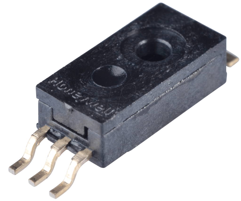
The HIH-4030 measures relative humidity (%RH) and does this by reporting DC voltage that is reflective of the relative humidity in near linear form.
The HIH-4030 humidity sensors is designed specifically for high volume OEM (Original Equipment Manufacturer) users. Direct input to a controller or other device is made possible by this sensor’s near linear voltage output. With a typical current draw of only 200 μA, the HIH-4030 Series is often ideally suited for low drain, battery operated systems.
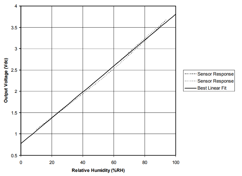
More details can be found here and if you don’t have time to read this this document it can be summarized with the following image, (did I mention near linear above?)
This sensor has three pins.
5V/VCC – 5V DC
GND – Ground
OUT – A return voltage (DC) which will be relative to the humidity it is reading.
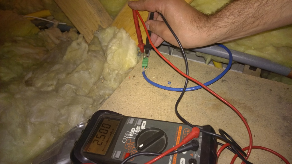
To test how the sensor operates you will need your multimeter and a DC power supply. Supply power to the sensor by connecting 5V and GND to the sensor. Then set your multimeter to DC volts and measure between GND and OUT. The reading you receive will now be relative to the humidity. As humidity changes so will be the voltage being displayed on your multimeter.
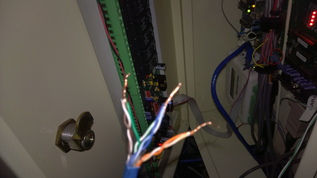
Step 2: Make The Connections
Once tested, connect the sensor to your microcontroller or PLC. When I built this house, I ran an abundance of Ethernet throughout the house. Rather than running a new cable I decided to use CAT 6 as my transport medium. As Cat 6 has 8 cores I have used 2 cores for GND, 3 cores for 5V and 3 cores for OUT. My cable run for each HIH-4030 in my house is approximately 25 meters.
The Honeywell HIH-4030 will require you to solder your cable to the sensor. Use heat shrink accordingly.
Step 3: Program And Test
With everything physically connected it is now time to program, tune and test. The sensor has an operating range which depending on your microcontroller will require a gain and offset value. Your mileage will vary based on the controller.
From the datasheet’s graph(above), it shows that at 0% RH you get a voltage of around 0.8V, at 100% RH you get 3.8V, and there is a near linear relationship between relative humidity and voltage.
The HomeVision Pro can apply gain and offset values to analog inputs.
These values are used to automatically adjust the analog input voltage value. This converts the raw value that is being read in (0 to 255) to a more meaningful value (in my case in %RH)
Final value = ( Input Value X Gain ) + Offset Value
The gain can range from 0 to 2.55 in increments of 0.01. The default value is 1.
The offset voltage can range from +127 to -128. The default value is 0.
The Homevision Pro can apply a gain and offset value to the analog values it measures which works well for a linear relationship. According to my calculations, using a gain of 0.65 and offset to -26, the analog port value you will be a pretty good approximation of the relative humidity.
This equation could be expressed as follows
255 * 0.8 / 5 * 0.65 – 26 = 0.52
I then tested by turning on the hot water in the shower and waiting. The RH% values should rise both with voltage on the OUT pin, but also the analogue values that your microcontroller is reading.
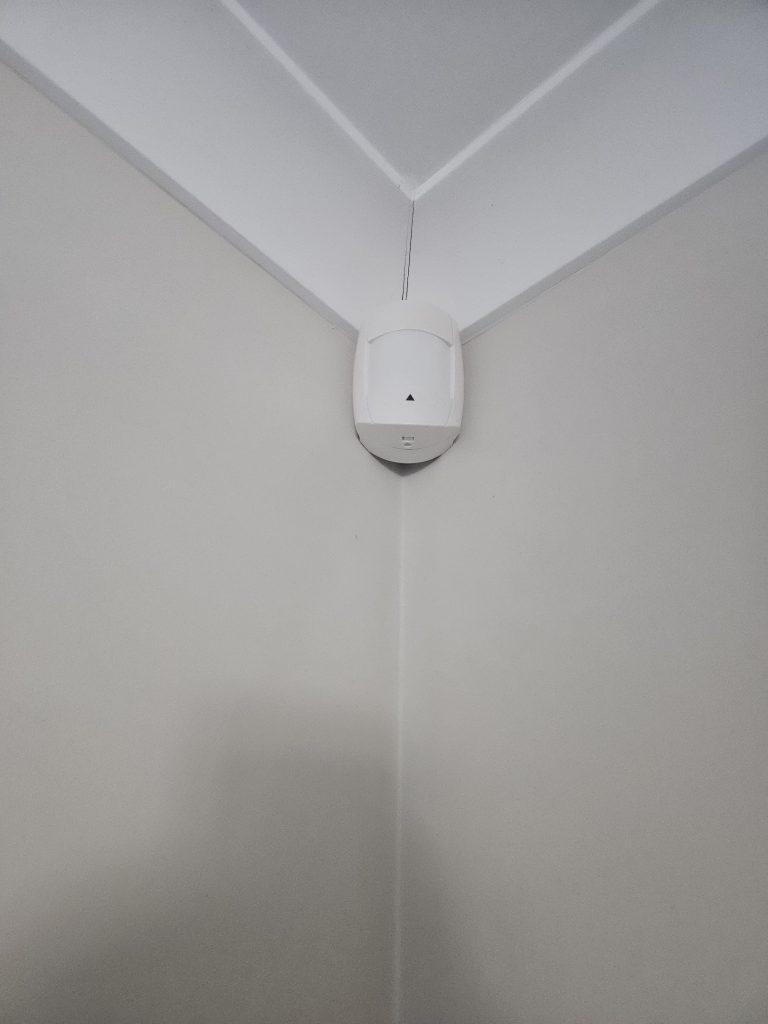
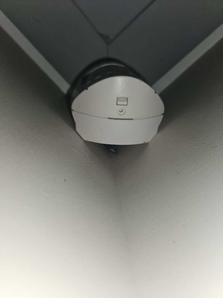
Step 4: Mount Your Sensor
I have multiple fans automated in my house and this is a generic pattern that I use. On one fan, I have this sensor hot glued to the back of the fan shroud (in the ceiling) and in another room, it is under the PIR (see pictures below). My suggestion is to find an aesthetically pleasing place for this sensor. Given my code (see below) is using sliding windows to measure change over time, it’s less important to have this sensor in the absolute best location. I don’t need absolute calibration; I just need to be able to keep it in the same room.
Step 5: Driving Your Fan (Relay or Appliance Module)
We can now read the relative humidity, excellent! That’s our input side done, and we will wrap this in MQTT and publish thee values to a MQTT topic. We now need to do something. That something is to drive a fan.
There is a plethora of ways to drive a fan. You could use an appliance module like a Shelly or a Sonoff and for the better part this would be reliable. But to make it really reliable and not rely on Wi-Fi (communication to the appliance module) and TCP/IP along with all the other layers that could go wrong I am using DPST (Dual Pole Single Throw) Omron relays. This relay will switch the active on the fan.
But I also want to have a fan switch that reflects the status of my fan (Clipsal 30PBL with a Sonoff Tasmota flashed appliance module)
Wiring modifications will need to be made at your fan switch. The fan will need to be no longer be switched at the fan switch (switched active), but switched active at the DPST relay.
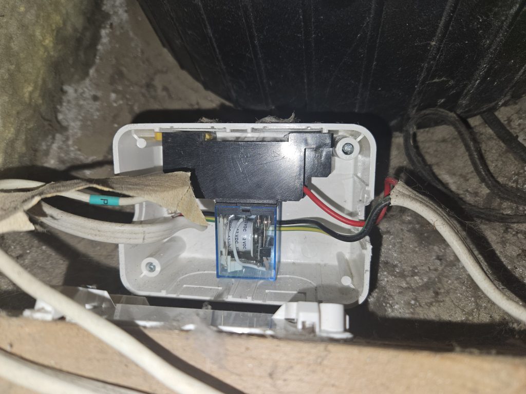
I have use a 12vDC /240AC Omron DPST. A cable needs to be ran from the PLC to the relay (switching side) with the relay switching the active going to the fan.
Step 6: Writing Code – It Actually Needs to Be Smart
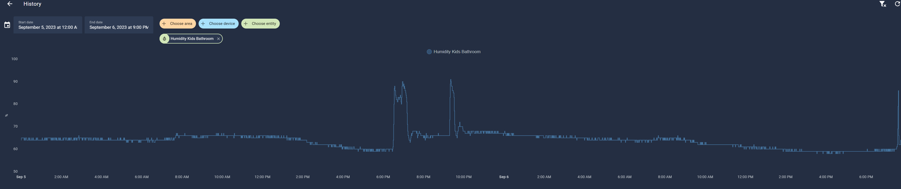
I am writing this post 5 years after I implemented this system. Initially I was triggering my fan based on a static RH (Relative Humidity). It will 99% of the time work just fine, but what happens when you get those really humid days? The result of weather like this is, the fan is stuck on until you change this statically defined threshold, not great.
We need a better way; we need sliding windows that compare periods. What I settled on is code that compares the RH% in one minute to the prior one-minutes RH%, if there is a change of more than 8% in under 1 minute then that’s our trigger. I settled on 8% as it’s enough to ensure fast triggering whilst not to high that we have false negatives.
; -----------------------------------------
; ANALOG HUMIDITY
; -----------------------------------------
; Kids Bathroom
Var #68 (Humidity - Analog Kid Bathroom) = Analog Input #0 (Humidity Sensor - Kid Bathroom)
If
   Var #68 (Humidity - Analog Kid Bathroom) > Var #88 (Humidty - Bathroom - Previous)
   Or Var #68 (Humidity - Analog Kid Bathroom) > 85
Then
   Load Timer #26 (PIR - Fan : U/S Bathroom) With 0:20:00:00 And Start
   If
      Timer #47 (Fan - U/S Activity) is running
   Then
      Set port A-6 (Fan - Kids) high (high)
   End If
End If
Var #88 (Humidty - Bathroom - Previous) = Analog Input #0 (Humidity Sensor - Kid Bathroom)
Var #88 (Humidty - Bathroom - Previous) = Var #88 (Humidty - Bathroom - Previous) + 10
; Ensuite
Var #83 (Humidity - Analog Ensuite) = Analog Input #1 (Humidity Sensor - Ensuite)
If
   Var #83 (Humidity - Analog Ensuite) > Var #87 (Humidty - Ensuite - Previous)
   Or Var #83 (Humidity - Analog Ensuite) > 97
Then
   Load Timer #44 (Fan - Ensuite Run Time) With 0:20:00:00 And Start
   If
      Timer #46 (Fan  - Ensuite Activity) is running
   Then
      Set port A-5 (Fan - Ensuite) high (high)
   End If
End If
Var #87 (Humidty - Ensuite - Previous) = Analog Input #1 (Humidity Sensor - Ensuite)
Var #87 (Humidty - Ensuite - Previous) = Var #87 (Humidty - Ensuite - Previous) + 10
; -----------------------------------------
; TIMER FOR HIH4030 - KIDS BATHROOM
; -----------------------------------------
If
	Timer #26 (PIR - Fan: U/S Bathroom) is ringing
Then
	Stop And Clear Timer #26 (PIR - Fan: U/S Bathroom)
	Set Port A-6 (Fan - Kids) low (low)
End If
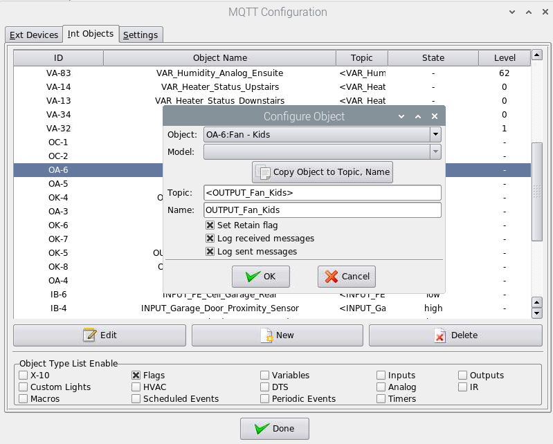
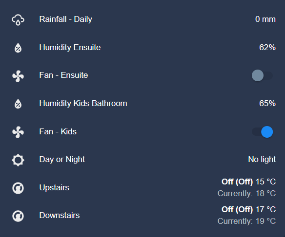
Step 7: Visualise with Home Assistant and MQTT
You could stop at Step 6, and this would be fine, it works. Humidity rises, the fan goes turn on, humidity drops, the fan turns off. But given we are driving this via MQTT messages it’s all too simple to have Home Assistant subscribe to the MQTT topics and visualize and provide additional control planes. I say an additional control plane as Home Assistant can send payloads to turn off the fan.
 #Humidity Sensors
    - name: "Humidity Kids Bathroom"
      unique_id: humidity_kidbathroom
      state_topic: "stat/VAR_Humidity_AnalogKidBathroom/RESULT"
      value_template: "{{ value_json.STATE }}"
      payload_available: "Online"
      payload_not_available: "Offline"
      device_class: humidity
      expire_after: 86400
      unit_of_measurement: "%"

#Fan
    - unique_id: fan_kids
      name: "Fan - Kids"
      state_topic: "stat/OUTPUT_Fan_Kids/RESULT"
      command_topic: "cmnd/OUTPUT_Fan_Kids/POWER"
      value_template: "{{ value_json.STATE }}"
      payload_on: "high"
      payload_off: "low"
      state_on: "high"
      state_off: "low"

    - unique_id: sonoff_tasmota_bathroom_fan
      name: "Sonoff - Bathroom Fan"
      state_topic: "stat/SONOFF_Tasmota_Bathroom/POWER2"
      command_topic: "cmnd/SONOFF_Tasmota_Bathroom/POWER2"
      value_template: "{{ value_json.STATE }}"
      payload_on: "ON"
      payload_off: "OFF"
      state_on: "ON"
      state_off: "OFF"
      qos: 2
Summary
Build systems that enrich your lives, work and are as dependable as a wood burning stove.
The Honeywell HIH-4030 is a great IC and when this just works, it’s like magic. This pattern will provide you a way to automatically turn your fans off and on, whilst providing a manual control plane.
Fan automation is real and will elevate your house from a science experiment to one that has your family raving. Get the soldering iron out and go and build.
Shane Baldacchino