I am the kind of person who operates on data. I also like tools and want to maintain them well. For many of my small engines I use hour meters to provide me the data to indicate when to perform maintenance . I was looking for a project of late and thought, what could I do with my air compressor in my tool shed.
So in this post we are going to modify an air compressor to
- Detect when the air compressor is refilling
- Count air compressor refill cycles
- Monitor the pressure set at the regulator
- Display metrics in Home Assistant
Parts & Software Required
- Pressure Transducer (Most compressors are 1/4″ BSPP or G1/4. I used this transducer from Amazon).
- MCU (Micro Controller Unit)
- MQTT Broker (Mosquitto, Hive or similar)
- Home Assistant
- Cable
- Soldering Iron + Solder + Flux + HeatShrink
- 5V PSU
- Multi Meter
Build Comments
If you read my posts (I hope you do) I am not a fan of wireless technologies. I will be using an Arduino Mega 2560v3 that is 30m away in a telco rack as the MCU with an PoE Ethernet Shied. I will be utilising an existing high current 5V PSU. I suggest not using the Arduino (or similar MCU or even a Raspberry PI‘s) 5V rail and to use a dedicated PSU. Whilst I am using a remote MCU, you could easily mount a local MCU and PSU to the compressor in an enclosure and use a form of wireless to transmit. A Wemos D1 would be a perfect MCU for this scenario. Wanting the clean look, I elected for the 30m run of cable and a connector on the sensor incase I need to temporary relocate the compressor.
The high level tasks we need to perform is
- Modification Of Air Compressor & Installation Of Pressure Transducer
- Test Sensor With Multi Meter
- Connect To MCU
- Arduino C++ Code – To Detect Pressure & Place Values On MQTT Bus
- Home Assistant Code – To Detect Refill Cycles
Pressure Transducer 101’s
The premise of the above is using a pressure transducer to measure pressure to which we will use to infer other functions (I’ll get to that).
A pressure transducer is a device that measures the pressure of a fluid, indicating the force the fluid is exerting on surfaces in contact with it and are used in many control and monitoring applications such as flow, air speed, level, pump systems or altitude.
To calculate pressure, the pressure transducer contains a force collector which is typically a flexible diaphragm which deforms when pressurised and a transduction element that transforms this deformation into an electrical signal.
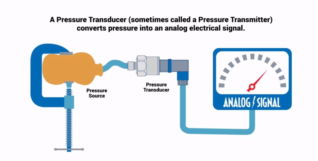
Inside the pressure transducer will be a strain gauge to measure the force acting on them. The strain gauges undergo deformation and this creates a change in voltage produced by it. The pressure measurement is based on the degree of change seen in the voltage.
Using our sensor we will send 5v and GND, with the analog return will linearly reflect the pressure detected as a DC voltage in which our Arduino MCU will interpret with code.
Modification Of Air Compressor & Installation Of Pressure Transducer
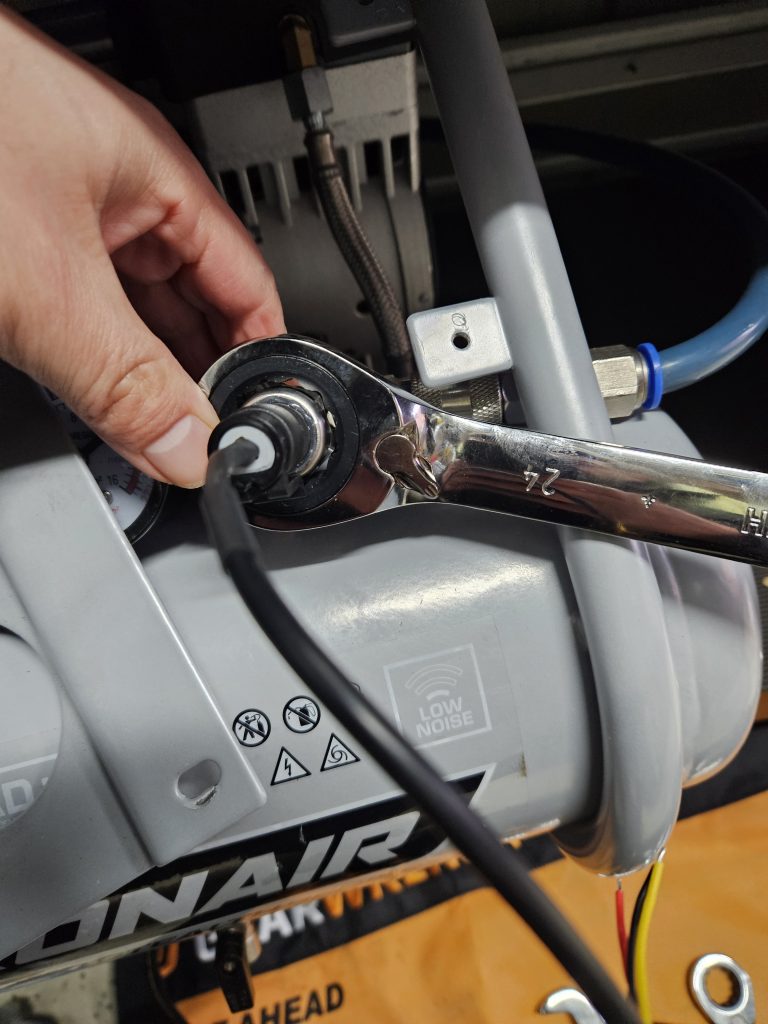
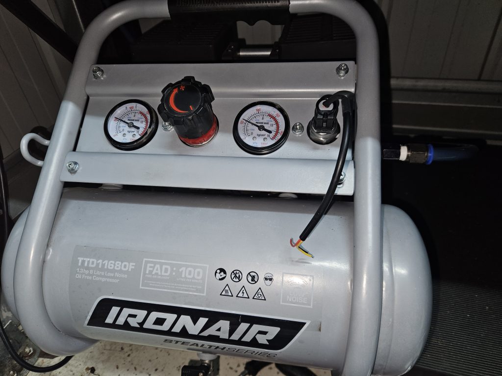
Your air compressor will most likely be different to my Iron Air 8L unit. You will need to disable the manifold. If your air compressor only has one output, you will need to use a splitter which are readily available. Insert your transducer in to your manifold and test to ensure there are no leaks before final reassembly.
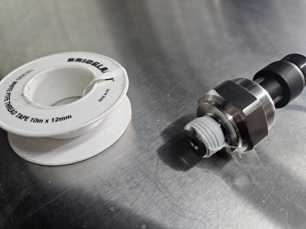
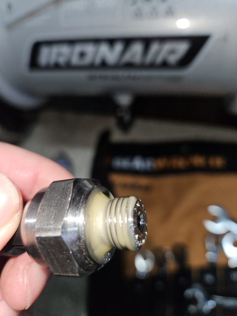
I had leaks initially using teflon tape, but that was solved by using Loxeal 58:11

Test Sensor With Multi Meter
Leaks resolved it’s time to test. I test, not by hooking up to the Arduino and my remote PSU but by using a standalone PSU. This could be like my Meanwell RS-15-5, or even a basic phone charger. Connect as follows.
| Pressure Transducer | Multi Meter | Power Supply |
| GND | COM | GND |
| VCC | VCC | |
| SIG | V |
You can use a cable connector or even twist wires together. Right now, we want to prove this is working, it does not need to be elegant.
Set your multi-meter to DC volts. As per the table above, your COM probe will be on the GND pin of either the PSU or Pressure Transducer and the V probe connected to the SIG pin of the Pressure Transducer.
This should yield a voltage between 0-5v based on the pressure that is being read. Use an air tool connected to the line. At this point as you consume air you should see voltage fluctuate.
You will notice that voltage moves around quite a lot. On my Fluke meter I was seeing voltage shift (2 and 3 decimals) quite a lot even when air was not being consumed. The ADC (Analogue To Digital Converter) on your MCU will notice this, dont worry we will address this in code.
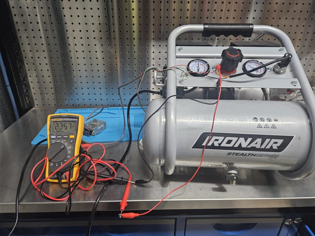
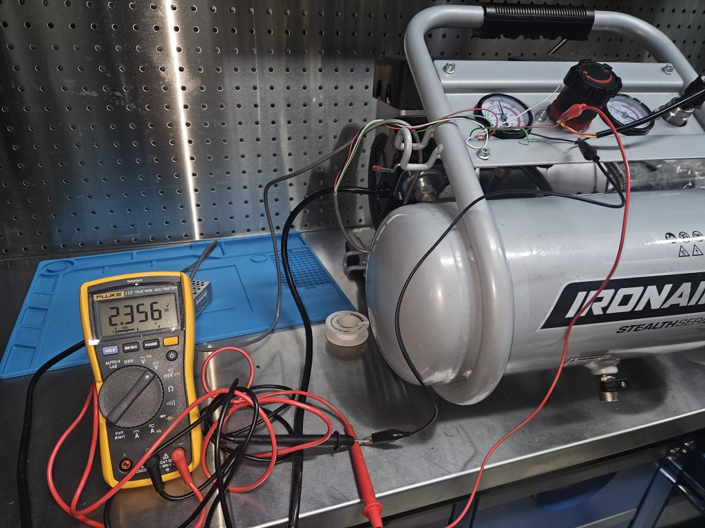
What I would also suggest, which wasted some time for myself, is to note down the voltage reading at the set PSI of your regulator. For example 80PSI is 2.845v, this will save time later when it comes to calibration.
Connect To MCU
After you have validated that the sensor is working correctly wire in to your MCU. As per the table above connect the GND to GND, VCC to VCC and the SIG to an Analogue Pin on the Arduino. You can use an Arduino or any MCU. My approach is to soldier and heat shrink each of the three connections than placing a piece of heat shrink over all three heat shrunk connections.
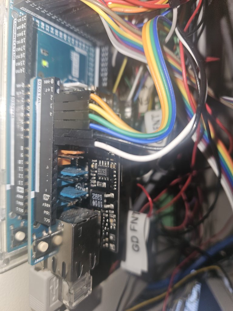
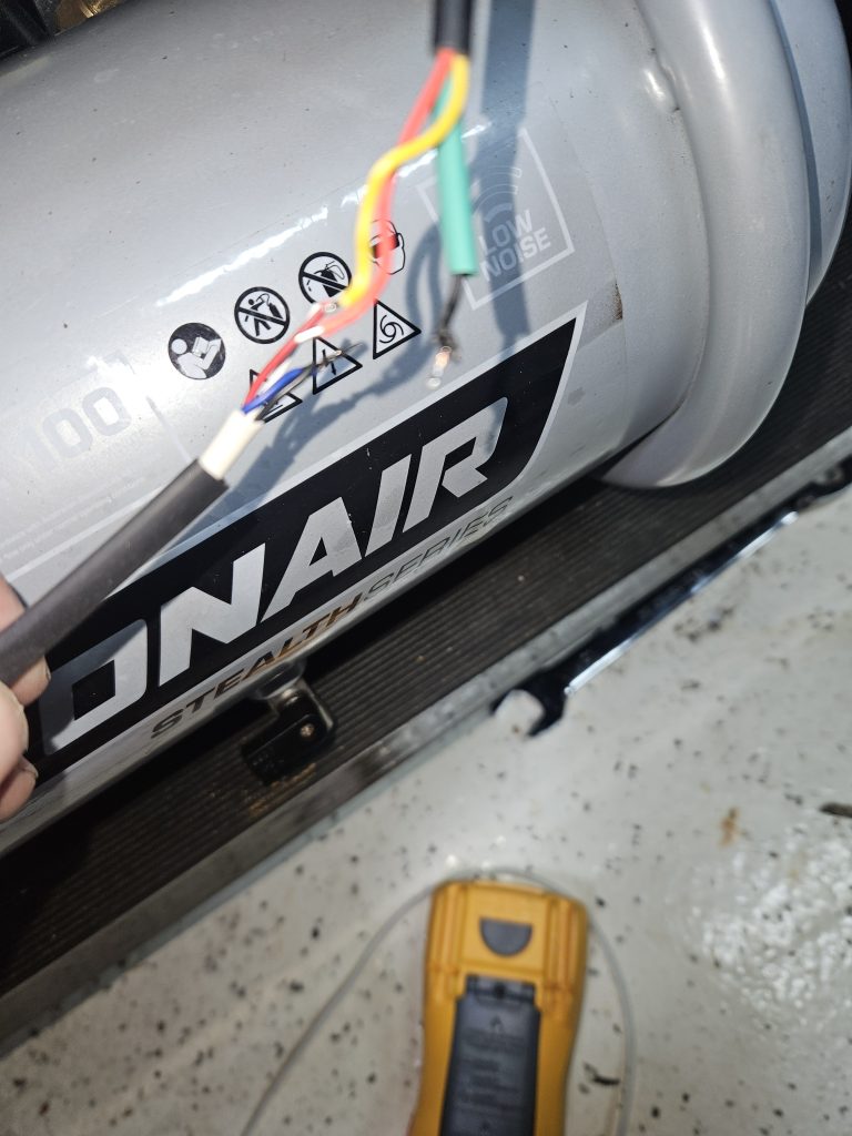
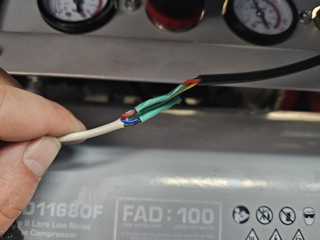
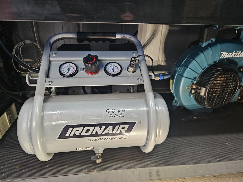
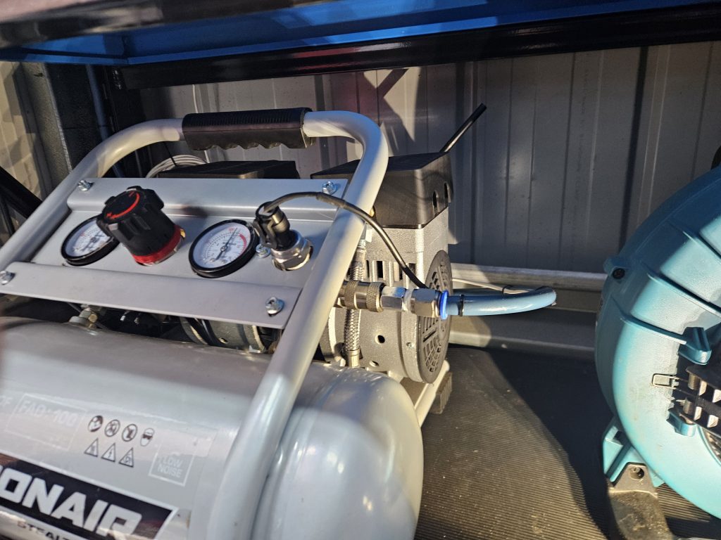
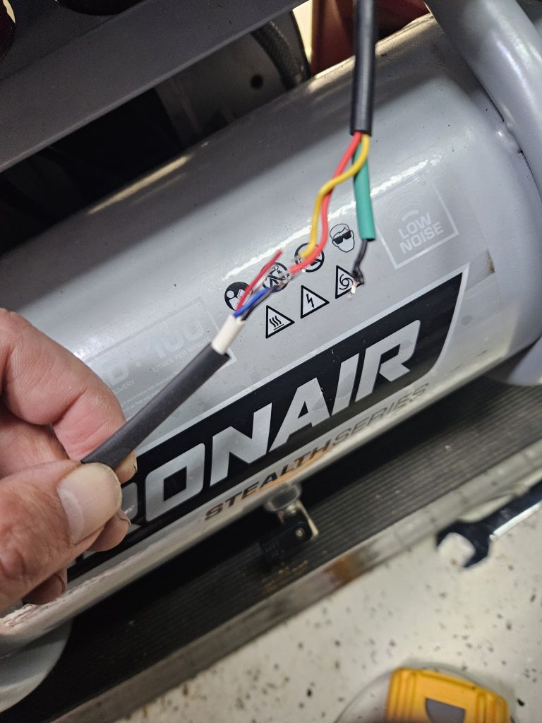
At this stage you should be able to create a sketch to read in the value from the analoge pin on your Ardunio. An example of this on its own would be as follows. Obviously this is standalone, but you could integrate this into your sketch.
// Define the analog pin
const int sensorPin = A0;

void setup() {
  // Start the serial communication
  Serial.begin(9600);
}

void loop() {
  // Read the analog value from the sensor
  int sensorValue = analogRead(sensorPin);

  // Convert the analog value to a voltage (0 to 5V)
  float voltage = sensorValue * (5.0 / 1023.0);

  // Print the voltage to the serial console
  Serial.print("Sensor Voltage: ");
  Serial.print(voltage);
  Serial.println(" V");

  // Small delay to avoid flooding the serial console
  delay(500);
}
Arduino C++ Code – To Detect Pressure & Place Values On MQTT Bus
The above code will read values from A0 and using the Arduino’s 10bit ADC (Analogue To Digital Converter) will convert the voltage in to an integer value between 0-1023.
We now need to turn this integer in to a PSI value and publish to the MQTT bus so Home Assistant will be able to leverage these pressure values.
The following code snippets are from my sketch and I have removed much of the bloat
In this block I am defining values in my setup. Calibration is important. I would suggest at this point setting your regulator to a PSI / KPA value you can clearly and easily read. Use your multimeter as per the process above to read the DC voltage value at a given PSI and adjust the code below. This will ensure the code below displays the correct PSI linear to the voltage. The DC voltage will be dependant on your transducer. My transducer reads from 0 to 170PSI. You can find transducers with shorter or wider ranges providing different levels of fidelity.
    const int pressurePin = A0;
    const float maxVoltage = 5.0;
    const float maxPSI = 170.0;
    const float calibrationVoltage = 2.884; // Voltage at 100 PSI
    const float calibrationPSI = 100.0; // PSI at calibration voltage
    const float calibrationFactor = calibrationPSI / calibrationVoltage;
    float lastPSI = -1;
    const float threshold = 2.5; // Change threshold to avoid spamming
The next process we need to do is establish a connection to your MQTT broker. My MQTT broker is at 10.0.0.200 and the following code in the function reconnect, connects to my MQTT broker and publishes a message of the Arduino’s local IP. I have removed all of my MQTT subscriptions, but you can also subscribe to have listen to messages, you will need handle these with a call back function.
//Start MQTT in establishment of HTTP
//IP Address of MQTT Server
IPAddress MQTTserver(10, 0, 0, 200);
// MQTT
EthernetClient ethClient2;
PubSubClient client2(ethClient2);


void reconnect() {
  // Loop until we're reconnected
  while (!client2.connected()) {
    Serial.print("Attempting MQTT connection...");
    // Attempt to connect
    if (client2.connect("arduinoClient")) {
      Serial.println("connected");
      // Once connected, publish an announcement...
      client2.publish("stat/ARDUINO/IP_Address","10.0.0.50");
      // ... and resubscribe


    } else {
      Serial.print("failed, rc=");
      Serial.print(client2.state());
      Serial.println(" try again in 5 seconds");
      // Wait 5 seconds before retrying
      delay(5000);
    }
  }
}
Lastly this code is in the main loop. If the compressor PSI value changes significantly (more than 2.5 PSI) the PSI is published to the MQTT topic stat/ARDUINO_Compressor/Psi with the PSI being the payload.
There is a lot going on but it is also quite simple. If you understand the process of leveraging MQTT on an Arduino, then this is pretty straight forward.
void loop() {


    //MQTT - Connect and Subscribe to Topics
    if (!client2.connected()) {
    reconnect();
    }

    // Send Data To Serial Port
    char inByte = ' ';
    if(Serial.available()){ // only send data back if data has been sent
      char inByte = Serial.read(); // read the incoming data
      Serial.println(inByte); // send the data back in a new line so that it is not all one long line
    }


    //Compressor Pressure Sensor (A0)
    int sensorValue = analogRead(pressurePin);
    float voltage = sensorValue * (maxVoltage / 1023.0);
    float psi = (voltage * calibrationFactor);

    // Only publish if the PSI value has changed significantly
    if (abs(psi - lastPSI) > threshold) {
      lastPSI = psi;
      char msg[50];
      dtostrf(psi, 6, 2, msg);
      client2.publish("stat/ARDUINO_Compressor/Psi", msg);
      Serial.print("Iron Air Compressor PSI: ");
      Serial.println(psi);
    }
}
I log to console to validate with the serial.println commands
09:02:17.946 -> Iron Air Compressor PSI: 98.63
09:02:18.037 -> Iron Air Compressor PSI: 101.68
09:02:18.037 -> Iron Air Compressor PSI: 98.63
09:02:18.037 -> Iron Air Compressor PSI: 94.40
09:02:18.100 -> Iron Air Compressor PSI: 98.80
09:02:18.100 -> Iron Air Compressor PSI: 96.26
09:02:18.174 -> Iron Air Compressor PSI: 99.99
Validating MQTT
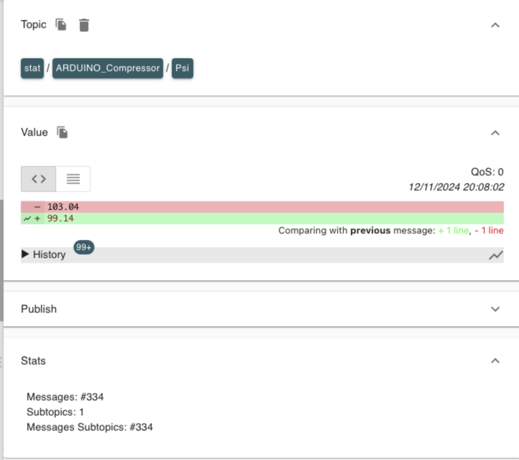
After compiling your sketch you will now see messages being published to your MQTT broker. The easiest way to validate this is to use a program like MQTT Explorer (available cross platform) rather than using mosquitto_sub.
Open up MQTT Explorer, navigate to your topic and you should see the PSI value as the payload of the topic. Use some air and you should see this instantly change, with the values being graphed. If you don’t see messages appear at your MQTT topic you will need to debug prior steps. I would check to ensure your topic path is correct and MQTT Broker details are valid (IP Address, TLS, Auth).

Displaying Data In Home Assistant
As the data is now in the MQTT Broker, we can now read this out of and display in a LoveLace dashboard.
The first process is to add the following to your configuration.yaml
mqtt:
  switch:
    - name: "Compressor Pressure"
      state_topic: "stat/ARDUINO_Compressor/Psi"
      unique_id: compressor_psi
      unit_of_measurement: "psi"
      expire_after: 86400
      value_template: "{{ value | float }}"
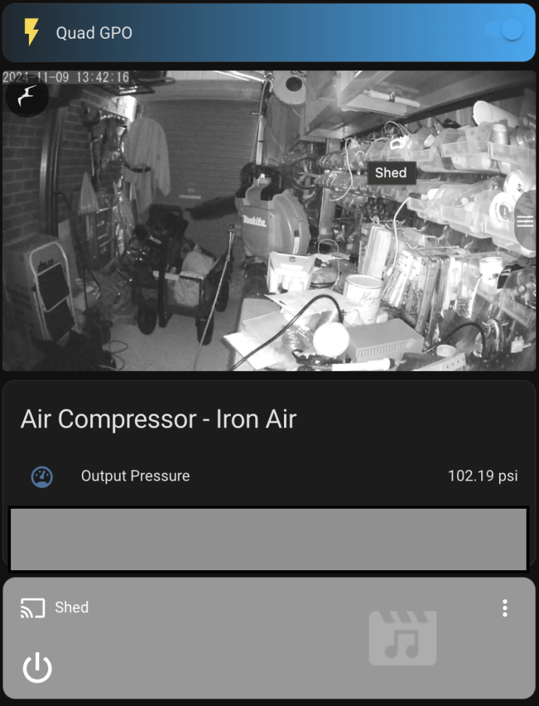
Restart Home Assistant. From here you will be able to create a LoveLace dashboard. I have blocked out a portion in this dashboard, we will get there in this post.. You can now see the PSI. If you use air, it should reflect in your LoveLace dashboard.
Calculating Refill Cycles
This is where we need to apply a little bit of logic. I am not going to use a current clamp, or appliance module for the reason I didn’t want to modify the compressor in any visible way. I like my automation stealth, so how can I count cycles. I can easily determine this by looking at other factors. By using an air gun the PSI will fluctuate at the regulator to the point where its can’t maintain pressure. That is our trigger. When PSI drops below a point that the regulator can not maintain (in my case around 85PSI) I will see pressure drop, then rise back-up as the tank if filled. Thats our signal.
If we are receiving a stream of PSI values in to our MQTT bus we can craft a Home Assistant Automation to detect and count the number of refill cycles. The Home Assistant Automation will store the value of refill cycles in an Input Helper. Create an Input Helper and define the minimum and maximum values.
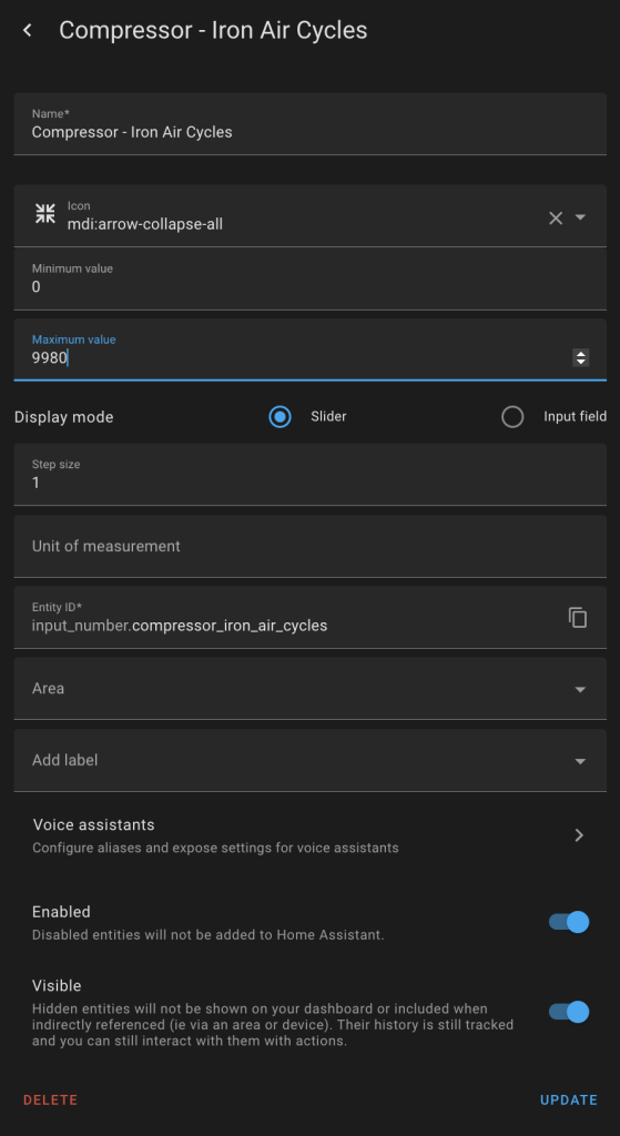
Now we can store values that will persist across reboots. It’s time to build a Home Assistant Automation. We will evaluate the MQTT entity (I called mine Compressor Pressure), evaluate the value of this entity and then increment our input helper. My automation looks like this, when the PSI value is < 84 (which appears to be the low value of my compressor when set to 100PSI), then increment the input helper.
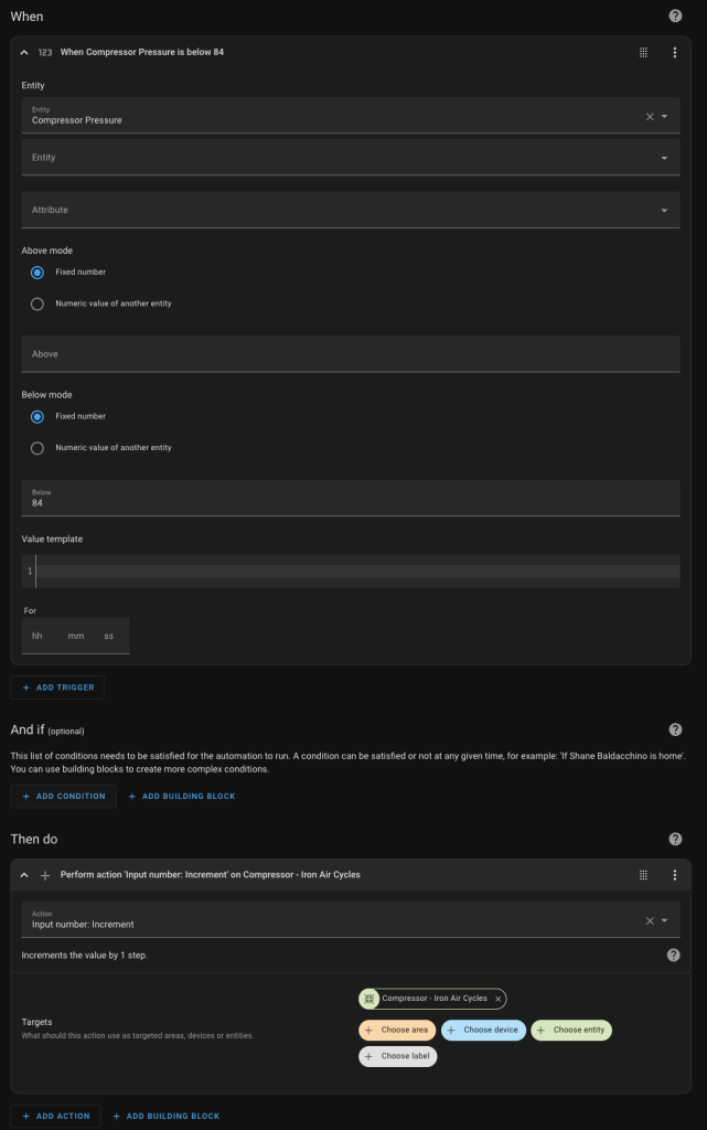
This can be represented as code
- id: '1727761269852'
  alias: Compressor - Iron Air Start
  description: ''
  trigger:
  - platform: numeric_state
    entity_id:
    - sensor.compressor_pressure
    below: 84
  condition: []
  action:
  - action: input_number.increment
    target:
      entity_id: input_number.compressor_iron_air_cycles
    data: {}
  mode: single
Testing
To test simply use your compressor. Two things you should notice.
- Home Assistant LoveLace dashboard PSI should fluctuate. It will either stay steady (but bounce around) or fall depending on the position of your transducer relative to your regulator, but you should see PSI change
- When your compressor starts to refill the tank, it will go below the defined threshold and you will see the input helper increment
Summary
Do we need this, of course not. Is it cool, I think so. More so it will be reliable. No batteries, no wireless and it’s another data point I can use for maintenance. This allows me to log duty cycles and monitor pressure in real time via Home Assistant using nothing but MQTT and an Arduino. Get your hands dirty and have a go because it’s easier than you think.
Thanks
Shane Baldacchino
