WARNING : Electricity can be lethal, this work should only be attempted by a licensed electrician
On my list of things to automate around my house is HVAC . This article is describes how I hooked a multi-zone heating system up to my Homevision Pro automation controller. It does not cover all of the programming and smarts around the installation. In reality this article will provide guidance for any automation system.
This modification will remove the thermostats off your walls. If you are uncomfortable in having your phone, tablet, computer or automation system controlling your heating then probably best you don’t continue. This setup has now been in place for 2 years without incident.
Bill of Materials
– 2 x 300ohm resistors ($1 AUD)
– 2 x SSR (Solid State Relays) 3.0 –> 32v DC switching AC 0 –> 500v AC ($20 AUD)
– 1 x Length of heat shrink ($3)
– 1 x 20m (enough cable to run between automation controller and heater furnace) of 6 core cable. ($10 AUD)
Total Cost = $34 AUD
Tools used
– Soldering Iron
– Pliers
– Screw Driver
– Drill and drill bits
Step 1: Figure out how the heater works?
Probably the most obvious step here for any automation task. Before we can emulate a wall thermostat we need to know what the wall thermostat is doing which tells the heater to turn on. Time to whip out the trusty multimeter. To figure out what the thermostat is doing I took the thermostat off the wall and begun probing for voltage and continuity. My system uses 3 wires (systems using heat pumps will use more)
G – Fan
R – 24V active
W – Heating
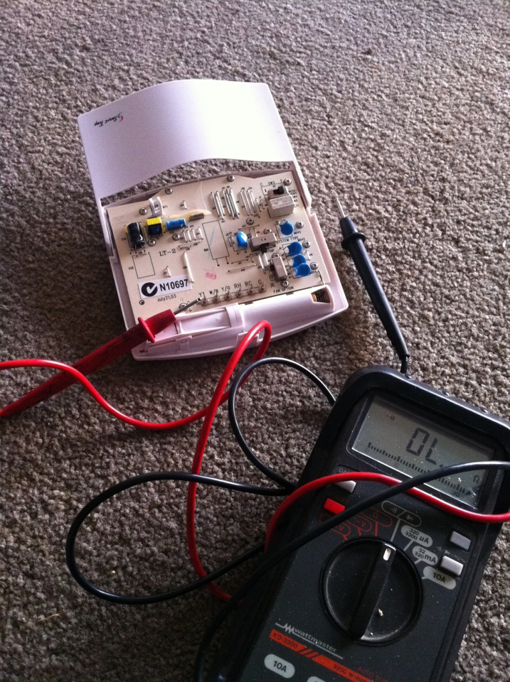
I observed when I manually moved the thermostat to a temperature above ambient I hear a click. This is almost a giveaway as this click is most likely a relay moving between NO or NC. So with the multimeter set to ‘continuity’ I started to probe.
What I found was when there was no request to provide heat, all connections were open between each pin. But when there is a request for heat that is higher than ambient their is continuity between G (Fan) and W (Heating).
The R is 24V and provides 24V to power the thermostat (unsure why it was wired in as this model runs off batteries). I don’t need it (as my automation controller is my thermostat) and thus am simply interested in just G and W. So what we need to do is bridge G and W together. To prove my theory I simply bridged G and W together and observed the output. The end result was we within a few minutes we had head coming out of the heating ducts. Success


Step 2: How to interface the HVPRO to the heater
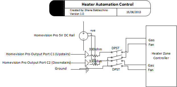
In order to interface the HomeVision Pro and the heating zone controller together I have elected to place a SSR in between to act as a buffer. It’s not needed as the Homevision Pro can drive the zone controller but I am doing this to prevent damage to HomeVision Pro should something go wrong. My house has multiple heating zones. So rather than running multiple cables for each zone I have ran a 6 core cable from the Homevision Pro to the heaters zone controller. I only require 3 cores (one for each relay and a shared common) but given how much hassle it can be to run cable I always recommend a few spare.
Step 3: Reducing the voltage
The SSR relays have a switching voltage of 3-32V DC. So I don’t have to introduce yet another PSU I wanted to use the 5VDC rail on the Homevision Pro. But if I use the 5V DC rail it will always be on and the house would get mighty hot :S. By using a 330ohm pull up resistor when the output port is high I get 3.2 volts (enough to switch the relay) and .7 of a volt when the port is low. Below is schematic of how this all plumbs together.